Inductive Reactance
Inductive reactance is the opposition to alternating current produced by inductance. The magnitude of inductance depends upon the rate of change of current.
Consider an inductor connected to an alternating voltage source. Let i and v be the instantaneous current and voltage respectively, V0 be the maximum voltage, and ω be the angular frequency, then:
v=V0sin(ωt)
Ldi/dt=V0sin(ωt)
di/dt=(V0/L)sin(ωt)
i=(V0/L)∫sin(ωt)
i=(-V0/(ωL))cos(ωt)
i=(V0/(ωL))sin(ωt-π/2)  [cos(θ)=-sin(θ-π/2)]
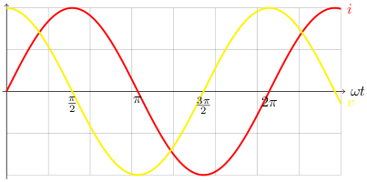
The graph below shows the relationship between current and voltage.
Inductive reactance is measured in ohms and written XL. Let I0 be the maximum current, then:
I0=V0/(ωL) [i is at its maximum when sin(ωt-π/2)=1]
ωL=V0/I0
  =XL
At high frequencies the induced emf is large and this restricts the current so the reactance will be greater than that at lower frequencies.
Practical Demonstration
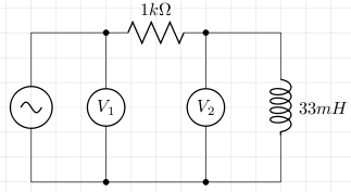
Consider the following circuit. V1 is measured by channel 1 on an oscilloscope, and V2 is measured by channel 2. The difference between them (V1 - V2) should give us the voltage across the resistor and according to Ohm's law, this is proportional to the current (in our case we just divide by 1000).
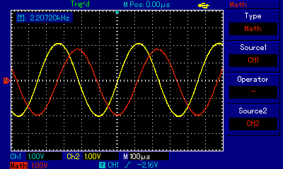
The screen shot from the oscilloscope shows the voltage across the resistor in red and the voltage across the inductor in yellow. We see that the voltage leads the current by π/2 and this is in agreement with the graph above.
References
Fischer-Cripps. A.C., The Electronics Companion. Institute of Physics, 2005.