Arithmetic Logic Unit (ALU)
An arithmetic logic unit (ALU) is combinational logic circuit which is typically used to implement a CPU's arithmetic and logic operations. An ALU will typically take one or two input operands and output a result along with a set of status bits. A selection input will determine the operation performed.
Arithmetic Operations
The set of arithmetic operations will include at least addition and subtraction. Some more basic designs have only an adder/subtractor circuit for the arithmetic part.
Logic Operations
Logic operations are usually implemented with the standard logic gates such as AND, OR etc. Obviously, the set of logic operations will need to be adequate, i.e. the programmer could use the set to implement any logic operation.
Status Bits
An ALU will typically output status bits indicating overflow, carry/borrow, negative result, and zero result. It is usually the case that all operations can set the zero result status bit, but only arithmetic operations can set the overflow, negative result and carry/borrow bits.
Example
Consider a basic 16-bit ALU which takes two operand inputs A and B, and generates the operation output Y
and the status bits C (Carry/borrow), V (oVerflow), N (Negative result), and Z (Zero result).
The 3-bit input Op will select the operation.
The specification for the ALU is given in the table below. The column labelled "meaning" shows us the operation at the
register transfer level in Verilog notation.
Op | Operation | Meaning |
|---|---|---|
000 | Add | Y <= A + B |
001 | Sub | Y <= A - B |
010 | And | Y <= A & B |
011 | Or | Y <= A | B |
100 | Exclusive or | Y <= A ^ B |
101 | Not | Y <= ~A |
110 | Unused | Y <= 0 |
111 | Unused | Y <= 0 |
To build this we will need a 16-bit adder/subtractor for the two arithmetic operations.
For the logic operations we will need a circuit for each operation (and, or, exclusive or, and not).
Each logic operation circuit will comprise 16 gates of the appropriate type.
Except for the not case, each gate takes one bit of each the two operands as its inputs and its output is one bit of the result.
In the case of not, the gate will only take input from the A operand.
The output of these arithmetic and logic circuits will need to be fed into a 16-bit wide 8-to-1 multiplexer.
The binary code shown in the table above (Op) will select the output and, as a consequence, the operation performed by the ALU.
The status bits C and V can be calculated by the adder/subtractor without much problem.
All that remains is some simple logic to select the adder/subtractor's C and V outputs when it is an arithmetic
operation, or binary zeroes if it is a logic operation.
The Z status output can be the output of a comparator which compares the multiplexer's
output with zero.
The N status is the most significant bit of the result which is the sign of a two's complement
value. This status bit is only set when the operation is an arithmetic operation.
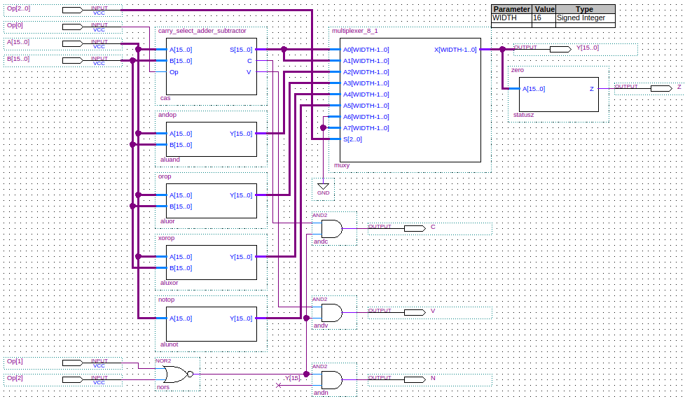
The schematic for this 16-bit ALU is shown below:
Verilog
Below is the Verilog code for a structural model of a basic 16-bit ALU. All code is shown for the supporting structures (multiplexers, full adders, etc.).
module alu(Y, C, V, N, Z, A, B, Op);
   output [15:0] Y;  // Result.
   output 	 C;  // Carry.
   output 	 N;  // Negative.
   output 	 V;  // Overflow.
   output 	 Z;  // Zero.
   input [15:0]  A;  // Operand.
   input [15:0]  B;  // Operand.
   input [2:0] 	 Op; // Operation.

   wire [15:0] 	 AS, And, Or, Xor, Not;
   wire 	 s;
   wire 	 Vas;
   wire 	 Cas;

   // The operations
   carry_select_adder_subtractor addsub(AS, Cas, Vas, A, B, Op[0]);      // Op == 3'b000, 3'b001
   andop aluand(And, A, B);                                              // Op == 3'b010
   orop aluor(Or, A, B);                                                 // Op == 3'b011
   xorop aluxor(Xor, A, B);                                              // Op == 3'b100
   notop alunot(Not, A);                                                 // Op == 3'b101
   multiplexer_8_1 muxy(Y, AS, AS, And, Or, Xor, Not, 16'b0, 16'b0, Op); // Select the result.

   nor(s, Op[1], Op[2]);   // s == 0 => a logical operation, otherwise and arithmetic operation.
   and(C, Cas, s);
   and(V, Vas, s);
   and(N, Y[15], s);       // Most significant bit is the sign bit in 2's complement.
   zero z(Z, Y);           // All operations can set the Zero status bit.
endmodule // alu

module andop(Y, A, B);
   output [15:0] Y;  // Result.
   input [15:0]  A;  // Operand.
   input [15:0]  B;  // Operand.

   and(Y[0], A[0], B[0]);
   and(Y[1], A[1], B[1]);
   and(Y[2], A[2], B[2]);
   and(Y[3], A[3], B[3]);
   and(Y[4], A[4], B[4]);
   and(Y[5], A[5], B[5]);
   and(Y[6], A[6], B[6]);
   and(Y[7], A[7], B[7]);
   and(Y[8], A[8], B[8]);
   and(Y[9], A[9], B[9]);
   and(Y[10], A[10], B[10]);
   and(Y[11], A[11], B[11]);
   and(Y[12], A[12], B[12]);
   and(Y[13], A[13], B[13]);
   and(Y[14], A[14], B[14]);
   and(Y[15], A[15], B[15]);
endmodule // andop

module orop(Y, A, B);
   output [15:0] Y; // Result.
   input [15:0]  A; // Operand.
   input [15:0]  B; // Operand.

   or(Y[0], A[0], B[0]);
   or(Y[1], A[1], B[1]);
   or(Y[2], A[2], B[2]);
   or(Y[3], A[3], B[3]);
   or(Y[4], A[4], B[4]);
   or(Y[5], A[5], B[5]);
   or(Y[6], A[6], B[6]);
   or(Y[7], A[7], B[7]);
   or(Y[8], A[8], B[8]);
   or(Y[9], A[9], B[9]);
   or(Y[10], A[10], B[10]);
   or(Y[11], A[11], B[11]);
   or(Y[12], A[12], B[12]);
   or(Y[13], A[13], B[13]);
   or(Y[14], A[14], B[14]);
   or(Y[15], A[15], B[15]);
endmodule // orop

module xorop(Y, A, B);
   output [15:0] Y; // Result.
   input [15:0]  A; // Operand.
   input [15:0]  B; // Operand.

   xor(Y[0], A[0], B[0]);
   xor(Y[1], A[1], B[1]);
   xor(Y[2], A[2], B[2]);
   xor(Y[3], A[3], B[3]);
   xor(Y[4], A[4], B[4]);
   xor(Y[5], A[5], B[5]);
   xor(Y[6], A[6], B[6]);
   xor(Y[7], A[7], B[7]);
   xor(Y[8], A[8], B[8]);
   xor(Y[9], A[9], B[9]);
   xor(Y[10], A[10], B[10]);
   xor(Y[11], A[11], B[11]);
   xor(Y[12], A[12], B[12]);
   xor(Y[13], A[13], B[13]);
   xor(Y[14], A[14], B[14]);
   xor(Y[15], A[15], B[15]);
endmodule // xorop

module notop(Y, A);
   output [15:0] Y; // Result.
   input [15:0]  A; // Operand.

   not(Y[0], A[0]);
   not(Y[1], A[1]);
   not(Y[2], A[2]);
   not(Y[3], A[3]);
   not(Y[4], A[4]);
   not(Y[5], A[5]);
   not(Y[6], A[6]);
   not(Y[7], A[7]);
   not(Y[8], A[8]);
   not(Y[9], A[9]);
   not(Y[10], A[10]);
   not(Y[11], A[11]);
   not(Y[12], A[12]);
   not(Y[13], A[13]);
   not(Y[14], A[14]);
   not(Y[15], A[15]);
endmodule // notop

module zero(Z, A);
   output Z;        // Result.
   input [15:0]  A; // Operand.

   wire [15:0] 	 Y; // Temp result.

   xnor(Y[0], A[0], 0);
   xnor(Y[1], A[1], 0);
   xnor(Y[2], A[2], 0);
   xnor(Y[3], A[3], 0);
   xnor(Y[4], A[4], 0);
   xnor(Y[5], A[5], 0);
   xnor(Y[6], A[6], 0);
   xnor(Y[7], A[7], 0);
   xnor(Y[8], A[8], 0);
   xnor(Y[9], A[9], 0);
   xnor(Y[10], A[10], 0);
   xnor(Y[11], A[11], 0);
   xnor(Y[12], A[12], 0);
   xnor(Y[13], A[13], 0);
   xnor(Y[14], A[14], 0);
   xnor(Y[15], A[15], 0);
   and(Z, Y[0], Y[1], Y[2], Y[3], Y[4],
       Y[5], Y[6], Y[7], Y[8],
       Y[9], Y[10], Y[11], Y[12],
       Y[13], Y[14], Y[15]);
endmodule // zero

module carry_select_adder_subtractor(S, C, V, A, B, Op);
   output [15:0] S;   // The 16-bit sum/difference.
   output 	 C;   // The 1-bit carry/borrow status.
   output 	 V;   // The 1-bit overflow status.
   input [15:0]  A;   // The 16-bit augend/minuend.
   input [15:0]  B;   // The 16-bit addend/subtrahend.
   input 	 Op;  // The operation: 0 => Add, 1=>Subtract.

   wire 	 C15; // The carry out bit of adder/subtractor, used to generate final carry/borrrow.
   wire [15:0] 	 Bx;

   // Looking at the truth table for not we see that
   // B xor 0 = B, and
   // B xor 1 = not(B).
   // So, if Op==1 means we are subtracting, then
   // adding A and B xor Op alog with setting the first
   // carry bit to Op, will give us a result of
   // A+B when Op==0, and A+not(B)+1 when Op==1.
   // Note that not(B)+1 is the 2's complement of B, so
   // this gives us subtraction.
   xor(Bx[0], B[0], Op);
   xor(Bx[1], B[1], Op);
   xor(Bx[2], B[2], Op);
   xor(Bx[3], B[3], Op);
   xor(Bx[4], B[4], Op);
   xor(Bx[5], B[5], Op);
   xor(Bx[6], B[6], Op);
   xor(Bx[7], B[7], Op);
   xor(Bx[8], B[8], Op);
   xor(Bx[9], B[9], Op);
   xor(Bx[10], B[10], Op);
   xor(Bx[11], B[11], Op);
   xor(Bx[12], B[12], Op);
   xor(Bx[13], B[13], Op);
   xor(Bx[14], B[14], Op);
   xor(Bx[15], B[15], Op);
   xor(C, C15, Op);            // Carry = C15 for addition, Carry = not(C15) for subtraction.
   carry_select_adder csa(S, C15, V, A, Bx, Op);
endmodule // carry_select_adder_subtractor

module carry_select_adder(S, C, V, A, B, Cin);
   output [15:0] S;   // The 16-bit sum.
   output 	 C;   // The 1-bit carry.
   output 	 V;   // The 1-bit overflow status.
   input [15:0]  A;   // The 16-bit augend.
   input [15:0]  B;   // The 16-bit addend.
   input 	 Cin; // The initial carry in.

   wire [3:0] 	S1_0;   // Nibble 1 sum output with carry input 0.
   wire [3:0] 	S1_1;   // Nibble 1 sum output with carry input 1.
   wire [3:0] 	S2_0;   // Nibble 2 sum output with carry input 0.
   wire [3:0] 	S2_1;   // Nibble 2 sum output with carry input 1.
   wire [3:0] 	S3_0;   // Nibble 3 sum output with carry input 0.
   wire [3:0] 	S3_1;   // Nibble 3 sum output with carry input 1.
   wire 	C1_0;   // Nibble 1 carry output with carry input 0.
   wire 	C1_1;   // Nibble 1 carry output with carry input 1.
   wire 	C2_0;   // Nibble 2 carry output with carry input 0.
   wire 	C2_1;   // Nibble 2 carry output with carry input 1.
   wire 	C3_0;   // Nibble 3 carry output with carry input 0.
   wire 	C3_1;   // Nibble 3 carry output with carry input 1.
   wire 	C0;     // Nibble 0 carry output used to select multiplexer output.
   wire 	C1;     // Nibble 1 carry output used to select multiplexer output.
   wire 	C2;     // Nibble 2 carry output used to select multiplexer output.
   wire         V0;     // Nibble 0 overflow output.
   wire 	V1_0;   // Nibble 1 overflow output with carry input 0.
   wire 	V1_1;   // Nibble 1 overflow output with carry input 1.
   wire 	V2_0;   // Nibble 2 overflow output with carry input 0.
   wire 	V2_1;   // Nibble 2 overflow output with carry input 1.
   wire 	V3_0;   // Nibble 3 overflow output with carry input 0.
   wire 	V3_1;   // Nibble 3 overflow output with carry input 1.

   ripple_carry_adder rc_nibble_0(S[3:0], C0, V0, A[3:0], B[3:0], Cin);          // Calculate S nibble 0.
   ripple_carry_adder rc_nibble_1_carry_0(S1_0, C1_0, V1_0, A[7:4], B[7:4], 0);      // Calculate S nibble 1 with carry input 0.
   ripple_carry_adder rc_nibble_1_carry_1(S1_1, C1_1, V1_1, A[7:4], B[7:4], 1);      // Calculate S nibble 1 with carry input 1.
   ripple_carry_adder rc_nibble_2_carry_0(S2_0, C2_0, V2_0, A[11:8], B[11:8], 0);    // Calculate S nibble 2 with carry input 0.
   ripple_carry_adder rc_nibble_2_carry_1(S2_1, C2_1, V2_1, A[11:8], B[11:8], 1);    // Calculate S nibble 2 with carry input 1.
   ripple_carry_adder rc_nibble_3_carry_0(S3_0, C3_0, V3_0, A[15:12], B[15:12], 0);  // Calculate S nibble 3 with carry input 0.
   ripple_carry_adder rc_nibble_3_carry_1(S3_1, C3_1, V3_1, A[15:12], B[15:12], 1);  // Calculate S nibble 3 with carry input 1.

   multiplexer_2_1 #(1) muxc1(C1, C1_0, C1_1, C0); // C0 selects the carry output for nibble 1.
   multiplexer_2_1 #(1) muxc2(C2, C2_0, C2_1, C1); // C1 selects the carry output for nibble 2.
   multiplexer_2_1 #(1) muxc(C, C3_0, C3_1, C2);   // C2 selects the carry output for nibble 3 which is the global carry output.
   multiplexer_2_1 #(1) muxv(V, V3_0, V3_1, C2);   // C2 selects the overflow output for nibble 3 which is the global overflow output.

   multiplexer_2_1 #(4) muxs1(S[7:4], S1_0, S1_1, C0);    // C0 selects the result for nibble 1.
   multiplexer_2_1 #(4) muxs2(S[11:8], S2_0, S2_1, C1);   // C1 selects the result for nibble 2.
   multiplexer_2_1 #(4) muxs3(S[15:12], S3_0, S3_1, C2);  // C2 selects the result for nibble 3.
endmodule // carry_select_adder

module ripple_carry_adder(S, C, V, A, B, Cin);
   output [3:0] S;   // The 4-bit sum.
   output 	C;   // The 1-bit carry.
   output       V;   // The 1-bit overflow status.
   input [3:0] 	A;   // The 4-bit augend.
   input [3:0] 	B;   // The 4-bit addend.
   input 	Cin; // The carry input.

   wire 	C0; // The carry out bit of fa0, the carry in bit of fa1.
   wire 	C1; // The carry out bit of fa1, the carry in bit of fa2.
   wire 	C2; // The carry out bit of fa2, the carry in bit of fa3.

   full_adder fa0(S[0], C0, A[0], B[0], Cin);    // Least significant bit.
   full_adder fa1(S[1], C1, A[1], B[1], C0);
   full_adder fa2(S[2], C2, A[2], B[2], C1);
   full_adder fa3(S[3], C, A[3], B[3], C2);    // Most significant bit.
   xor(V, C, C2);  // Overflow
endmodule // ripple_carry_adder

module full_adder(S, Cout, A, B, Cin);
   output S;
   output Cout;
   input  A;
   input  B;
   input  Cin;

   wire   w1;
   wire   w2;
   wire   w3;
   wire   w4;

   xor(w1, A, B);
   xor(S, Cin, w1);
   and(w2, A, B);
   and(w3, A, Cin);
   and(w4, B, Cin);
   or(Cout, w2, w3, w4);
endmodule // full_adder

module multiplexer_2_1(X, A0, A1, S);
   parameter WIDTH=16;     // How many bits wide are the lines

   output [WIDTH-1:0] X;   // The output line

   input [WIDTH-1:0]  A1;  // Input line with id 1'b1
   input [WIDTH-1:0]  A0;  // Input line with id 1'b0
   input 	      S;  // Selection bit

   assign X = (S == 1'b0) ? A0 : A1;
endmodule // multiplexer_2_1

module multiplexer_8_1(X, A0, A1, A2, A3, A4, A5, A6, A7, S);
   parameter WIDTH=16;     // How many bits wide are the lines

   output [WIDTH-1:0] X;   // The output line

   input [WIDTH-1:0]  A7;  // Input line with id 3'b111
   input [WIDTH-1:0]  A6;  // Input line with id 3'b110
   input [WIDTH-1:0]  A5;  // Input line with id 3'b101
   input [WIDTH-1:0]  A4;  // Input line with id 3'b100
   input [WIDTH-1:0]  A3;  // Input line with id 3'b011
   input [WIDTH-1:0]  A2;  // Input line with id 3'b010
   input [WIDTH-1:0]  A1;  // Input line with id 3'b001
   input [WIDTH-1:0]  A0;  // Input line with id 3'b000
   input [2:0]	      S;

   assign X = (S[2] == 0
	       ? (S[1] == 0
		  ? (S[0] == 0
		     ? A0       // {S2,S1,S0} = 3'b000
		     : A1)      // {S2,S1,S0} = 3'b001
		  : (S[0] == 0
		     ? A2       // {S2,S1,S0} = 3'b010
		     : A3))     // {S2,S1,S0} = 3'b011
	       : (S[1] == 0
		  ? (S[0] == 0
		     ? A4       // {S2,S1,S0} = 3'b100
		     : A5)      // {S2,S1,S0} = 3'b101
		  : (S[0] == 0
		     ? A6       // {S2,S1,S0} = 3'b110
		     : A7)));   // {S2,S1,S0} = 3'b111
endmodule // multiplexer_8_1
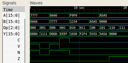
When given test inputs, the 16-bit adder/subtractor generated the following waveform:
References
Mano, M. Morris, and Kime, Charles R. Logic and Computer Design Fundamentals. 2nd Edition. Prentice Hall, 2000.