D Latch
A D latch is used to store one bit of data. It is an example of a sequential logic circuit. The D latch is essentially a modification of the gated SR latch.
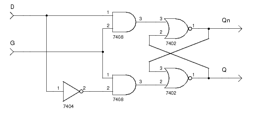
The schematic below shows a D latch.
The input D is the data to be stored.
The input G is used to control the storing.
The outputs Q and Qn are the stored data and the complement of the stored data respectively.
Example
The following function table shows the operation of a D latch.
G |
D |
Q |
Qn |
Meaning |
|---|---|---|---|---|
0 | 0 | Q | Qn | Hold |
0 | 1 | Q | Qn | Hold |
1 | 0 | 0 | 1 | Reset |
1 | 1 | 1 | 0 | Set |
Verilog
Below is the Verilog code for a structural model of a D latch.
module d_latch(Q, Qn, G, D);
   output Q;
   output Qn;
   input  G;
   input  D;

   wire   Dn;
   wire   D1;
   wire   Dn1;

   not(Dn, D);
   and(D1, G, D);
   and(Dn1, G, Dn);
   nor(Qn, D1, Q);
   nor(Q, Dn1, Qn);
endmodule
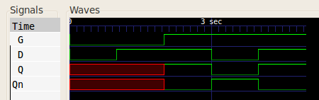
A simulation with test inputs gave the following wave form:
References
Kleitz, W. Digital Microprocessor Fundamentals. 3rd Edition. Prentice Hall, 2000.
Mano, M. Morris, and Kime, Charles R. Logic and Computer Design Fundamentals. 2nd Edition. Prentice Hall, 2000.