High Pass Filter
The high pass filter attenuates low frequencies and lets high frequencies through. We can build such a filter with a RC circuit or a RL circuit.
RC Circuit
The basic circuit using a resistor and a capacitor is as follows:
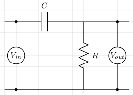
Let XC be the capacitive reactance and ω be the angular frequency. To calculate the cut-off frequency we proceed as follows:
Vin = IZ
Vout = IR
Vout/Vin = R/√(R2+XC2)
   = R/√(R2+1/(ω2C2)   [Multiply top and bottom by RωC]
   = RωC/√(1+R2ω2C2)
Now, at the cut-off frequency,
1/√2 = RωC/√(1+R2ω2C2)
RωC = 1
Example
Taking a 1kΩ resistor and a 100nF capacitor we can calculate ω at the cut-off frequency which will give us the cut-off frequency, f, when we divide that by 2π. So,
C = 100nF = 1×10⁻⁷
R = 1kΩ = 1×10³
RC = 1×10⁻⁴
ω = 1/RC = 1×10⁴
f = ω/2π = 1.590kHz
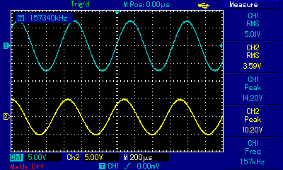
The circuit was built and both Vin and Vout were measured with an oscilloscope at various frequencies. Vin was supplied by a signal generator. The first measurement was taken at roughly the cut-off frequency of 1.59kHz. In the image below, channel 1 (blue trace) is Vin and the channel 2 (yellow trace) is Vout. As expected, Vout/Vin is roughly 0.7.
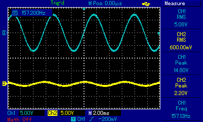
The next measurement was taken at a frequency of roughly 157Hz which is much lower than the cut-off frequency of 1.59kHz. This low frequency signal is attenuated.
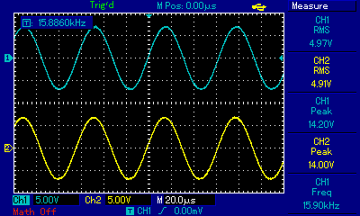
The last measurement was taken at a frequency of roughly 15.9kHz which is much higher than the cut-off frequency of 1.59kHz. As expected, Vout/Vin is roughly 1. This signal is passing through the filter.
RL Circuit
The basic circuit using a resistor and an inductor is as follows:
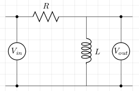
Let XL be the inductive reactance and ω be the angular frequency. To calculate the cut-off frequency we proceed as follows:
Vin = IZ = I√(R2+ω2L2)
Vout = IXL = ωL
Vout/Vin = ωL/√(R2+ω2L2)
   = 1/√(R2/ω2L2+1)
Now, at the cut-off frequency,
1/√2 = 1/√(R2/ω2L2+1)
R2/ω2L2 = 1
Example
Taking a 1kΩ resistor and a 85mH inductor we can calculate ω at the cut-off frequency which will give us the cut-off frequency, f, when we divide that by 2π. So,
L = 0.085H
R = 1kΩ
ω = R/L = 11764.7
f = ω/2π = 1.873kHz
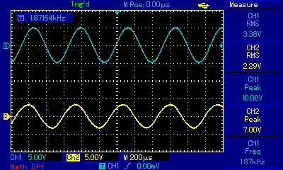
The circuit was built and both Vin and Vout were measured with an oscilloscope at various frequencies. Vin was supplied by a signal generator. The first measurement was taken at roughly the cut-off frequency of 1.87kHz. In the image below, channel 1 (blue trace) is Vin and the channel 2 (yellow trace) is Vout. As expected, Vout/Vin is roughly 0.7.
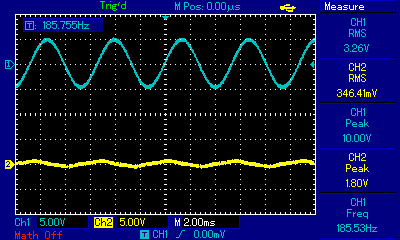
The next measurement was taken at a frequency of roughly 187Hz which is much lower than the cut-off frequency of 1.87kHz. This low frequency signal is attenuated.
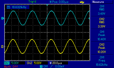
The last measurement was taken at a frequency of roughly 18.7kHz which is much higher than the cut-off frequency of 1.87kHz. As expected, Vout/Vin is roughly 1. This signal is passing through the filter.
References
Fischer-Cripps. A.C., The Electronics Companion. Institute of Physics, 2005.