Flip-Flop Input Equation
The combinational logic circuit inputs to a flip-flop are described by a flip-flop input Boolean equation.
Example
Consider the following sequential logic circuit containing a JK flip-flop and a D flip-flop (not all connections are shown to keep the schematic simple):
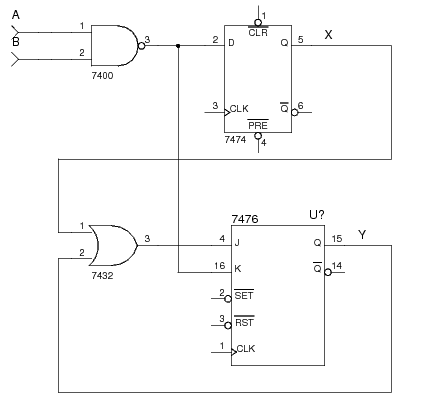
The D flip-flop has output X. Its input has no name, so let's call its input DX.
The JK flip-flop has output Y. Its inputs also have no names so let's call them
JY, and KY.
We can then give formulas for the combinational logic inputs of each flip-flop input as follows:
DX = A nand BJY = X or YKY = A nand B
References
Mano, M. Morris, and Kime, Charles R. Logic and Computer Design Fundamentals. 2nd Edition. Prentice Hall, 2000.