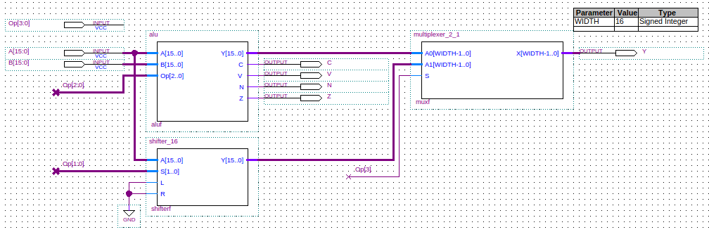
Function Unit
A function unit comprises an ALU and a shifter.
For its inputs, the function unit takes two values and a function code to select the operation which will be performed upon these values.
These inputs are passed onto the ALU and the shifter.
Internally, there is a multiplexer which selects either the ALU's output or the shifter's output to
be the function unit's output.
The function unit will also output all of the ALU's status bit outputs: C (Carry), V (oVerflow),
N (Negative), and Z (Zero result).
Example
Consider a 16-bit function unit with inputs A and B.
The result output we will call Y.
The following table gives the specification for the function unit. The second column shows the operation performed at the
register transfer level using Verilog notation.
| Function code | Operation |
|---|---|
0000 | Y = A + B |
0001 | Y = A - B |
0010 | Y = A & B |
0011 | Y = A | B |
0100 | Y = A ^ B |
0101 | Y = ~A |
0110 | Y = 0 |
0111 | Y = 0 |
1000 | Y = A |
1001 | Y = A << 1 |
1010 | Y = A >> 1 |
1011 | Undefined |
1100 | Undefined |
1101 | Undefined |
1110 | Undefined |
1111 | Undefined |
The schematic form of the function unit is:
Below is the full Verilog code for the function unit.
module function_unit(Y, C, V, N, Z, A, B, Op);
   output [15:0] Y;  // Result.
   output 	 C;  // Carry.
   output 	 N;  // Negative.
   output 	 V;  // Overflow.
   output 	 Z;  // Zero.
   input [15:0]  A;  // Operand.
   input [15:0]  B;  // Operand.
   input [3:0] 	 Op; // Operation.

   wire [15:0] 	 Ya; // ALU result output.
   wire [15:0] 	 Ys; // Shifter result output.

   alu aluf(Ya, C, V, N, Z, A, B, {Op[2], Op[1], Op[0]});
   shifter_16 shifterf(Ys, A, {Op[1], Op[0]}, 1'b0, 1'b0);
   multiplexer_2_1 muxf(Y, Ya, Ys, Op[3]);
endmodule // function_unit

module alu(Y, C, V, N, Z, A, B, Op);
   output [15:0] Y;  // Result.
   output 	 C;  // Carry.
   output 	 N;  // Negative.
   output 	 V;  // Overflow.
   output 	 Z;  // Zero.
   input [15:0]  A;  // Operand.
   input [15:0]  B;  // Operand.
   input [2:0] 	 Op; // Operation.

   wire [15:0] 	 AS, And, Or, Xor, Not;
   wire 	 s;
   wire 	 Vas;
   wire 	 Cas;

   // The operations
   carry_select_adder_subtractor addsub(AS, Cas, Vas, A, B, Op[0]);      // Op == 3'b000, 3'b001
   andop aluand(And, A, B);                                              // Op == 3'b010
   orop aluor(Or, A, B);                                                 // Op == 3'b011
   xorop aluxor(Xor, A, B);                                              // Op == 3'b100
   notop alunot(Not, A);                                                 // Op == 3'b101
   multiplexer_8_1 muxy(Y, AS, AS, And, Or, Xor, Not, 16'b0, 16'b0, Op); // Select the result.

   nor(s, Op[1], Op[2]);   // s == 0 => a logical operation, otherwise and arithmetic operation.
   and(C, Cas, s);
   and(V, Vas, s);
   and(N, Y[15], s);       // Most significant bit is the sign bit in 2's complement.
   zero z(Z, Y);           // All operations can set the Zero status bit.
endmodule // alu

module andop(Y, A, B);
   output [15:0] Y;  // Result.
   input [15:0]  A;  // Operand.
   input [15:0]  B;  // Operand.

   and(Y[0], A[0], B[0]);
   and(Y[1], A[1], B[1]);
   and(Y[2], A[2], B[2]);
   and(Y[3], A[3], B[3]);
   and(Y[4], A[4], B[4]);
   and(Y[5], A[5], B[5]);
   and(Y[6], A[6], B[6]);
   and(Y[7], A[7], B[7]);
   and(Y[8], A[8], B[8]);
   and(Y[9], A[9], B[9]);
   and(Y[10], A[10], B[10]);
   and(Y[11], A[11], B[1]);
   and(Y[12], A[12], B[12]);
   and(Y[13], A[13], B[13]);
   and(Y[14], A[14], B[14]);
   and(Y[15], A[15], B[15]);
endmodule // andop

module orop(Y, A, B);
   output [15:0] Y; // Result.
   input [15:0]  A; // Operand.
   input [15:0]  B; // Operand.

   or(Y[0], A[0], B[0]);
   or(Y[1], A[1], B[1]);
   or(Y[2], A[2], B[2]);
   or(Y[3], A[3], B[3]);
   or(Y[4], A[4], B[4]);
   or(Y[5], A[5], B[5]);
   or(Y[6], A[6], B[6]);
   or(Y[7], A[7], B[7]);
   or(Y[8], A[8], B[8]);
   or(Y[9], A[9], B[9]);
   or(Y[10], A[10], B[10]);
   or(Y[11], A[11], B[1]);
   or(Y[12], A[12], B[12]);
   or(Y[13], A[13], B[13]);
   or(Y[14], A[14], B[14]);
   or(Y[15], A[15], B[15]);
endmodule // orop

module xorop(Y, A, B);
   output [15:0] Y; // Result.
   input [15:0]  A; // Operand.
   input [15:0]  B; // Operand.

   xor(Y[0], A[0], B[0]);
   xor(Y[1], A[1], B[1]);
   xor(Y[2], A[2], B[2]);
   xor(Y[3], A[3], B[3]);
   xor(Y[4], A[4], B[4]);
   xor(Y[5], A[5], B[5]);
   xor(Y[6], A[6], B[6]);
   xor(Y[7], A[7], B[7]);
   xor(Y[8], A[8], B[8]);
   xor(Y[9], A[9], B[9]);
   xor(Y[10], A[10], B[10]);
   xor(Y[11], A[11], B[1]);
   xor(Y[12], A[12], B[12]);
   xor(Y[13], A[13], B[13]);
   xor(Y[14], A[14], B[14]);
   xor(Y[15], A[15], B[15]);
endmodule // xorop

module notop(Y, A);
   output [15:0] Y; // Result.
   input [15:0]  A; // Operand.

   not(Y[0], A[0]);
   not(Y[1], A[1]);
   not(Y[2], A[2]);
   not(Y[3], A[3]);
   not(Y[4], A[4]);
   not(Y[5], A[5]);
   not(Y[6], A[6]);
   not(Y[7], A[7]);
   not(Y[8], A[8]);
   not(Y[9], A[9]);
   not(Y[10], A[10]);
   not(Y[11], A[11]);
   not(Y[12], A[12]);
   not(Y[13], A[13]);
   not(Y[14], A[14]);
   not(Y[15], A[15]);
endmodule // notop

module zero(Z, A);
   output Z;        // Result.
   input [15:0]  A; // Operand.

   wire [15:0] 	 Y; // Temp result.

   xnor(Y[0], A[0], 0);
   xnor(Y[1], A[1], 0);
   xnor(Y[2], A[2], 0);
   xnor(Y[3], A[3], 0);
   xnor(Y[4], A[4], 0);
   xnor(Y[5], A[5], 0);
   xnor(Y[6], A[6], 0);
   xnor(Y[7], A[7], 0);
   xnor(Y[8], A[8], 0);
   xnor(Y[9], A[9], 0);
   xnor(Y[10], A[10], 0);
   xnor(Y[11], A[11], 0);
   xnor(Y[12], A[12], 0);
   xnor(Y[13], A[13], 0);
   xnor(Y[14], A[14], 0);
   xnor(Y[15], A[15], 0);
   and(Z, Y[0], Y[1], Y[2], Y[3], Y[4],
       Y[5], Y[6], Y[7], Y[8],
       Y[9], Y[10], Y[11], Y[12],
       Y[13], Y[14], Y[15]);
endmodule // zero

module carry_select_adder_subtractor(S, C, V, A, B, Op);
   output [15:0] S;   // The 16-bit sum/difference.
   output 	 C;   // The 1-bit carry/borrow status.
   output 	 V;   // The 1-bit overflow status.
   input [15:0]  A;   // The 16-bit augend/minuend.
   input [15:0]  B;   // The 16-bit addend/subtrahend.
   input 	 Op;  // The operation: 0 => Add, 1=>Subtract.

   wire 	 C15; // The carry out bit of adder/subtractor, used to generate final carry/borrrow.
   wire [15:0] 	 Bx;

   // Looking at the truth table for not we see that
   // B xor 0 = B, and
   // B xor 1 = not(B).
   // So, if Op==1 means we are subtracting, then
   // adding A and B xor Op alog with setting the first
   // carry bit to Op, will give us a result of
   // A+B when Op==0, and A+not(B)+1 when Op==1.
   // Note that not(B)+1 is the 2's complement of B, so
   // this gives us subtraction.
   xor(Bx[0], B[0], Op);
   xor(Bx[1], B[1], Op);
   xor(Bx[2], B[2], Op);
   xor(Bx[3], B[3], Op);
   xor(Bx[4], B[4], Op);
   xor(Bx[5], B[5], Op);
   xor(Bx[6], B[6], Op);
   xor(Bx[7], B[7], Op);
   xor(Bx[8], B[8], Op);
   xor(Bx[9], B[9], Op);
   xor(Bx[10], B[10], Op);
   xor(Bx[11], B[11], Op);
   xor(Bx[12], B[12], Op);
   xor(Bx[13], B[13], Op);
   xor(Bx[14], B[14], Op);
   xor(Bx[15], B[15], Op);
   xor(C, C15, Op);            // Carry = C15 for addition, Carry = not(C15) for subtraction.
   carry_select_adder csa(S, C15, V, A, Bx, Op);
endmodule // carry_select_adder_subtractor

module carry_select_adder(S, C, V, A, B, Cin);
   output [15:0] S;   // The 16-bit sum.
   output 	 C;   // The 1-bit carry.
   output 	 V;   // The 1-bit overflow status.
   input [15:0]  A;   // The 16-bit augend.
   input [15:0]  B;   // The 16-bit addend.
   input 	 Cin; // The initial carry in.

   wire [3:0] 	S1_0;   // Nibble 1 sum output with carry input 0.
   wire [3:0] 	S1_1;   // Nibble 1 sum output with carry input 1.
   wire [3:0] 	S2_0;   // Nibble 2 sum output with carry input 0.
   wire [3:0] 	S2_1;   // Nibble 2 sum output with carry input 1.
   wire [3:0] 	S3_0;   // Nibble 3 sum output with carry input 0.
   wire [3:0] 	S3_1;   // Nibble 3 sum output with carry input 1.
   wire 	C1_0;   // Nibble 1 carry output with carry input 0.
   wire 	C1_1;   // Nibble 1 carry output with carry input 1.
   wire 	C2_0;   // Nibble 2 carry output with carry input 0.
   wire 	C2_1;   // Nibble 2 carry output with carry input 1.
   wire 	C3_0;   // Nibble 3 carry output with carry input 0.
   wire 	C3_1;   // Nibble 3 carry output with carry input 1.
   wire 	C0;     // Nibble 0 carry output used to select multiplexer output.
   wire 	C1;     // Nibble 1 carry output used to select multiplexer output.
   wire 	C2;     // Nibble 2 carry output used to select multiplexer output.
   wire         V0;     // Nibble 0 overflow output.
   wire 	V1_0;   // Nibble 1 overflow output with carry input 0.
   wire 	V1_1;   // Nibble 1 overflow output with carry input 1.
   wire 	V2_0;   // Nibble 2 overflow output with carry input 0.
   wire 	V2_1;   // Nibble 2 overflow output with carry input 1.
   wire 	V3_0;   // Nibble 3 overflow output with carry input 0.
   wire 	V3_1;   // Nibble 3 overflow output with carry input 1.

   ripple_carry_adder rc_nibble_0(S[3:0], C0, V0, A[3:0], B[3:0], Cin);          // Calculate S nibble 0.
   ripple_carry_adder rc_nibble_1_carry_0(S1_0, C1_0, V1_0, A[7:4], B[7:4], 0);      // Calculate S nibble 1 with carry input 0.
   ripple_carry_adder rc_nibble_1_carry_1(S1_1, C1_1, V1_1, A[7:4], B[7:4], 1);      // Calculate S nibble 1 with carry input 1.
   ripple_carry_adder rc_nibble_2_carry_0(S2_0, C2_0, V2_0, A[11:8], B[11:8], 0);    // Calculate S nibble 2 with carry input 0.
   ripple_carry_adder rc_nibble_2_carry_1(S2_1, C2_1, V2_1, A[11:8], B[11:8], 1);    // Calculate S nibble 2 with carry input 1.
   ripple_carry_adder rc_nibble_3_carry_0(S3_0, C3_0, V3_0, A[15:12], B[15:12], 0);  // Calculate S nibble 3 with carry input 0.
   ripple_carry_adder rc_nibble_3_carry_1(S3_1, C3_1, V3_1, A[15:12], B[15:12], 1);  // Calculate S nibble 3 with carry input 1.

   multiplexer_2_1 #(1) muxc1(C1, C1_0, C1_1, C0); // C0 selects the carry output for nibble 1.
   multiplexer_2_1 #(1) muxc2(C2, C2_0, C2_1, C1); // C1 selects the carry output for nibble 2.
   multiplexer_2_1 #(1) muxc(C, C3_0, C3_1, C2);   // C2 selects the carry output for nibble 3 which is the global carry output.
   multiplexer_2_1 #(1) muxv(V, V3_0, V3_1, C2);   // C2 selects the overflow output for nibble 3 which is the global overflow output.

   multiplexer_2_1 #(4) muxs1(S[7:4], S1_0, S1_1, C0);    // C0 selects the result for nibble 1.
   multiplexer_2_1 #(4) muxs2(S[11:8], S2_0, S2_1, C1);   // C1 selects the result for nibble 2.
   multiplexer_2_1 #(4) muxs3(S[15:12], S3_0, S3_1, C2);  // C2 selects the result for nibble 3.
endmodule // carry_select_adder

module ripple_carry_adder(S, C, V, A, B, Cin);
   output [3:0] S;   // The 4-bit sum.
   output 	C;   // The 1-bit carry.
   output       V;   // The 1-bit overflow status.
   input [3:0] 	A;   // The 4-bit augend.
   input [3:0] 	B;   // The 4-bit addend.
   input 	Cin; // The carry input.

   wire 	C0; // The carry out bit of fa0, the carry in bit of fa1.
   wire 	C1; // The carry out bit of fa1, the carry in bit of fa2.
   wire 	C2; // The carry out bit of fa2, the carry in bit of fa3.

   full_adder fa0(S[0], C0, A[0], B[0], Cin);    // Least significant bit.
   full_adder fa1(S[1], C1, A[1], B[1], C0);
   full_adder fa2(S[2], C2, A[2], B[2], C1);
   full_adder fa3(S[3], C, A[3], B[3], C2);    // Most significant bit.
   xor(V, C, C2);  // Overflow
endmodule // ripple_carry_adder

module full_adder(S, Cout, A, B, Cin);
   output S;
   output Cout;
   input  A;
   input  B;
   input  Cin;

   wire   w1;
   wire   w2;
   wire   w3;
   wire   w4;

   xor(w1, A, B);
   xor(S, Cin, w1);
   and(w2, A, B);
   and(w3, A, Cin);
   and(w4, B, Cin);
   or(Cout, w2, w3, w4);
endmodule // full_adder

module multiplexer_2_1(X, A0, A1, S);
   parameter WIDTH=16;     // How many bits wide are the lines

   output [WIDTH-1:0] X;   // The output line

   input [WIDTH-1:0]  A1;  // Input line with id 1'b1
   input [WIDTH-1:0]  A0;  // Input line with id 1'b0
   input 	      S;  // Selection bit

   assign X = (S == 1'b0) ? A0 : A1;
endmodule // multiplexer_2_1

module multiplexer_4_1(X, A0, A1, A2, A3, S1, S0);
   parameter WIDTH=16;     // How many bits wide are the lines

   output [WIDTH-1:0] X;   // The output line

   input [WIDTH-1:0]  A3;  // Input line with id 2'b11
   input [WIDTH-1:0]  A2;  // Input line with id 2'b10
   input [WIDTH-1:0]  A1;  // Input line with id 2'b01
   input [WIDTH-1:0]  A0;  // Input line with id 2'b00
   input 	      S0;  // Least significant selection bit
   input 	      S1;  // Most significant selection bit

   assign X = (S1 == 0
	       ? (S0 == 0
		  ? A0       // {S1,S0} = 2'b00
		  : A1)      // {S1,S0} = 2'b01
	       : (S0 == 0
		  ? A2       // {S1,S0} = 2'b10
		  : A3));    // {S1,S0} = 2'b11
endmodule // multiplexer_4_1

module multiplexer_8_1(X, A0, A1, A2, A3, A4, A5, A6, A7, S);
   parameter WIDTH=16;     // How many bits wide are the lines

   output [WIDTH-1:0] X;   // The output line

   input [WIDTH-1:0]  A7;  // Input line with id 3'b111
   input [WIDTH-1:0]  A6;  // Input line with id 3'b110
   input [WIDTH-1:0]  A5;  // Input line with id 3'b101
   input [WIDTH-1:0]  A4;  // Input line with id 3'b100
   input [WIDTH-1:0]  A3;  // Input line with id 3'b011
   input [WIDTH-1:0]  A2;  // Input line with id 3'b010
   input [WIDTH-1:0]  A1;  // Input line with id 3'b001
   input [WIDTH-1:0]  A0;  // Input line with id 3'b000
   input [2:0]	      S;

   assign X = (S[2] == 0
	       ? (S[1] == 0
		  ? (S[0] == 0
		     ? A0       // {S2,S1,S0} = 3'b000
		     : A1)      // {S2,S1,S0} = 3'b001
		  : (S[0] == 0
		     ? A2       // {S2,S1,S0} = 3'b010
		     : A3))     // {S2,S1,S0} = 3'b011
	       : (S[1] == 0
		  ? (S[0] == 0
		     ? A4       // {S2,S1,S0} = 3'b100
		     : A5)      // {S2,S1,S0} = 3'b101
		  : (S[0] == 0
		     ? A6       // {S2,S1,S0} = 3'b110
		     : A7)));   // {S2,S1,S0} = 3'b111
endmodule // multiplexer_8_1

module shifter_16(Y, A, S, L, R);
   output [15:0] Y;  // The shifted result.
   input [15:0]  A;  // The value to be shifted.
   input [1:0] 	 S;  // The direction of the shift.
   input 	 L;  // The leftmost bit to shift in.
   input 	 R;  // The rightmost bit to shift in.

   multiplexer_4_1 #(1) mux0(Y[0], A[0], A[1], L, 1'b0, S[1], S[0]);
   multiplexer_4_1 #(1) mux1(Y[1], A[1], A[2], A[0], 1'b0, S[1], S[0]);
   multiplexer_4_1 #(1) mux2(Y[2], A[2], A[3], A[1], 1'b0, S[1], S[0]);
   multiplexer_4_1 #(1) mux3(Y[3], A[3], A[4], A[2], 1'b0, S[1], S[0]);
   multiplexer_4_1 #(1) mux4(Y[4], A[4], A[5], A[3], 1'b0, S[1], S[0]);
   multiplexer_4_1 #(1) mux5(Y[5], A[5], A[6], A[4], 1'b0, S[1], S[0]);
   multiplexer_4_1 #(1) mux6(Y[6], A[6], A[7], A[5], 1'b0, S[1], S[0]);
   multiplexer_4_1 #(1) mux7(Y[7], A[7], A[8], A[6], 1'b0, S[1], S[0]);
   multiplexer_4_1 #(1) mux8(Y[8], A[8], A[9], A[7], 1'b0, S[1], S[0]);
   multiplexer_4_1 #(1) mux9(Y[9], A[9], A[10], A[8], 1'b0, S[1], S[0]);
   multiplexer_4_1 #(1) mux10(Y[10], A[10], A[11], A[9], 1'b0, S[1], S[0]);
   multiplexer_4_1 #(1) mux11(Y[11], A[11], A[12], A[10], 1'b0, S[1], S[0]);
   multiplexer_4_1 #(1) mux12(Y[12], A[12], A[13], A[11], 1'b0, S[1], S[0]);
   multiplexer_4_1 #(1) mux13(Y[13], A[13], A[14], A[12], 1'b0, S[1], S[0]);
   multiplexer_4_1 #(1) mux14(Y[14], A[14], A[15], A[13], 1'b0, S[1], S[0]);
   multiplexer_4_1 #(1) mux15(Y[15], A[15], R, A[14], 1'b0, S[1], S[0]);
endmodule // shifter_16
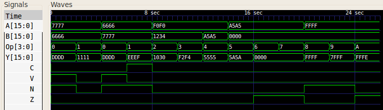
The function unit gave the following waveform when test inputs were given:
References
Mano, M. Morris, and Kime, Charles R. Logic and Computer Design Fundamentals. 2nd Edition. Prentice Hall, 2000.