State Table
A state table shows the current state, inputs, next state, and outputs of a sequential logic circuit. It shows the same information as can be found in a state diagram.
Example
Consider the following Mealy model sequential logic circuit containing a single D flip-flop (not all connections are shown to keep the schematic simple):
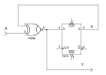
The sole input is A and the sole output is Y.
With one flip-flop we have two (21=2) different states (X=0 and X=1).
We can write the flip-flop input equation for the D flip-flop with output X as:
DX = A xnor X.
The Boolean equation for the output is Y = A xnor X.
Using these we can create the following table:
| Current State | Input | Next State | Output |
|---|---|---|---|
X |
A |
X |
Y |
0 |
0 |
1 |
1 |
0 |
1 |
0 |
0 |
1 |
0 |
0 |
0 |
1 |
1 |
1 |
1 |
References
Mano, M. Morris, and Kime, Charles R. Logic and Computer Design Fundamentals. 2nd Edition. Prentice Hall, 2000.